Blink an external led with ESP8266
Overview
Teaching: 0 min
Exercises: 0 minQuestions
How to use an external led with an ESP8266?
How to write a program to blink an external led?
Objectives
Become familar with ESP8266
Create a circuit with an external led and ESP8266
Write a program to blink an external led with an ESP8266
Now that your ESP8266 is fully installed and working on your laptop, we can start to add an external led and control it via a program.
Using GPIOs of the ESP8266
Before using an available GPIO (General Purpose Input/Output) from our ESP8266 board, let’s have a look at them:
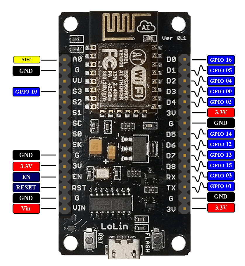
- Vin to supply power to the ESP8266 (as a standalone device, without your laptop)
- GND Ground pins all connected together and serve as a 0V reference
- ADC Input for the built-in analog to digital convert (8bits)
- GPIOXX are general purpose digital inputs and outputs pins (some of them can be modulated for outputs)
LED (light-Emitting Diode)
A LED is an electronic component which glows when a voltage is applied.

Be careful the led has to be connected in the correct direction otherwise it will be damaged.
The correct direction is:
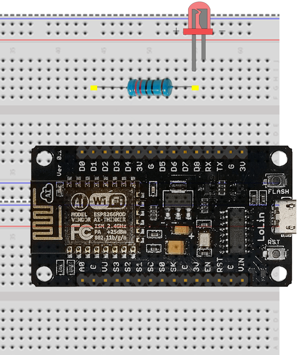
- short leg (-) connected to GND
- long leg (+) connected to the power supply but not directly. A resistor must be introduced (in series) in order to limit the maximum current crossing the junction (inside the LED).
In our example, a 220 Ohm will be used (I = U / R = 3.3 / 220 = 0.015 A = 15 mA).
- First disconnect the ESP8266 from your computer (disconnect USB).
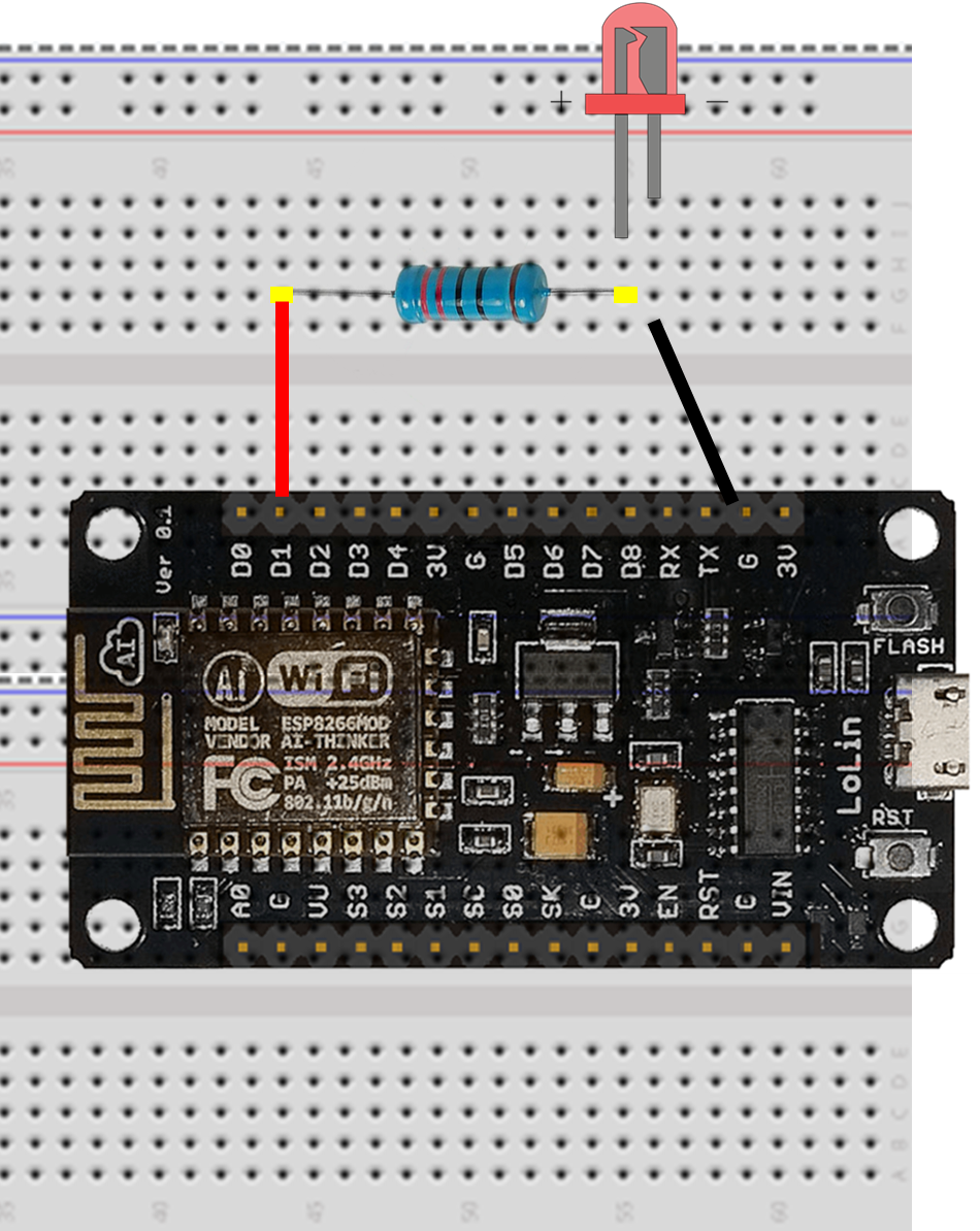
Use the breadboard and the wires to connect the resistor, the LED and the ESP8266 together as follow:
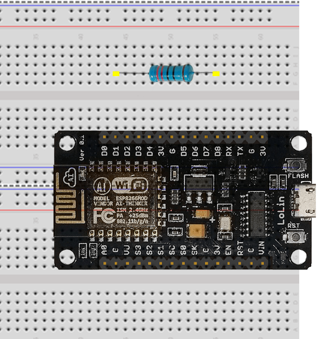
- Bend (gently) the 2 legs of the resistor (to make a U) and place it on the breadboard on two parallel rows; one of which needs to be inline with the GPIO 5 (D1 on the ESP8266) as shown on the picture
- Place the long leg (+) of the LED in a hole on the same row as the resistor as shown on the figure below.
- Connect the short leg (-) of the LED to the ground (GND) using a black wire as shown on the figure below.
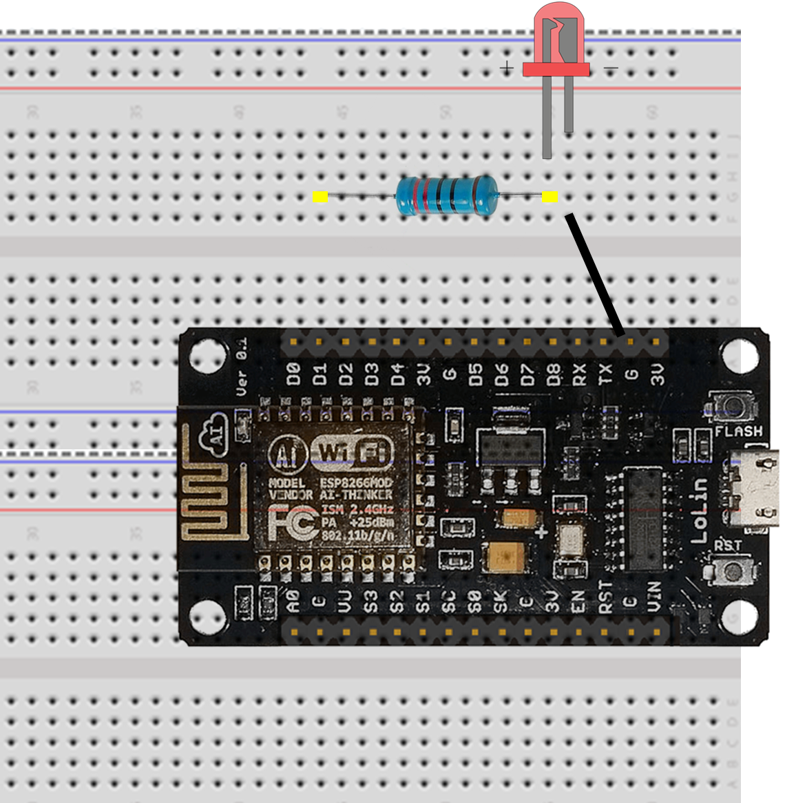
- Connect the first leg of the resistor using a second wire (red) to the GPIO 5 of the ESP8266 (D1).
Tips for the breadboard
Breadboards consist of tiny “holes” in which the leads of the component connect into.

But holes are not all connected to each others.
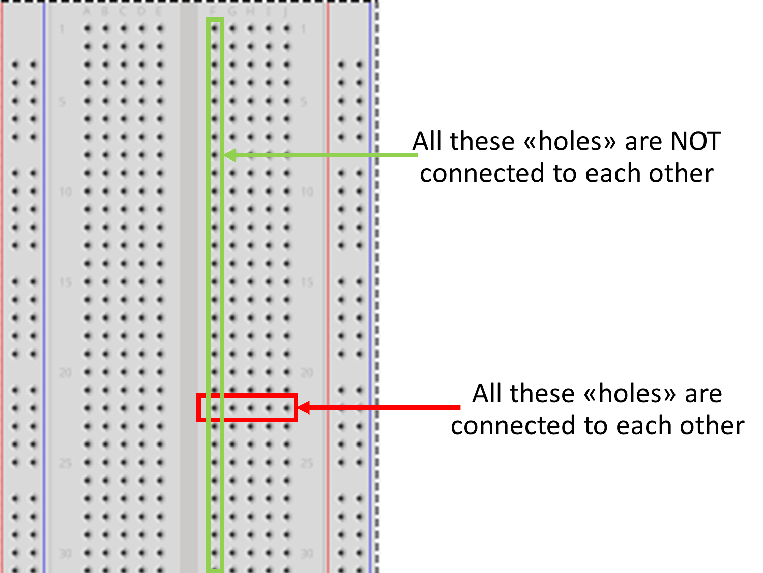
More information can be found here
Check your electronic circuit before running your programm.
Run your program
- Take your previous Blink code and replace LED_PIN = 2 by LED_PIN = 5
- Connect your ESP8266 to your computer via the USB port
-
Recompile and upload
- You can also change delay (for instance 100 and 2000).
If everything is OK, your LED should blink!
Key Points
Use a breadboard and an external led
Write and run a program to blink an external led